|
scmn | Larger ground wires would help far more than more ground rods.
The trouble with stray voltage is the misconception that there are perfect conductors and perfect insulators. A perfect conductor would have no resistance to electrical flow and thus no losses and a perfect insulator would pass no electrical current.
In the real world, conductors have resistance that is dissipated as heat. The NEC stipulates the minimum wire size for a given current to keep wire heating below a certain temperature to protect wires from getting too hot and burning down structures. At the same time that resistance in a wire creates heat, it also creates voltage drop. This results in most long runs using wire that is much higher ampacity to prevent excess voltage drop that results in performance issues. The line losses and resistance are accounted for in the NEC.
When you look at insulators in the real world, everyone assumes they are perfect insulators, which is not true. There are no perfect insulators that exists at normal atmospheric conditions. Some insulators are much better than others, but none are perfect. What that means in even though we stuck an insulated wire in the ground, a portion of the current is restricted to the wire, but a minuscule amount of that current escapes thru the insulation, flows into the ground and then seeks a path back to the source (power plant). Some of the current seeks a direct straight line, while some will try to go around the world back to the substation, the more direct the route (shorter), the higher the current and the longer the route the lower the current. The current is also affected by soil conductivity.
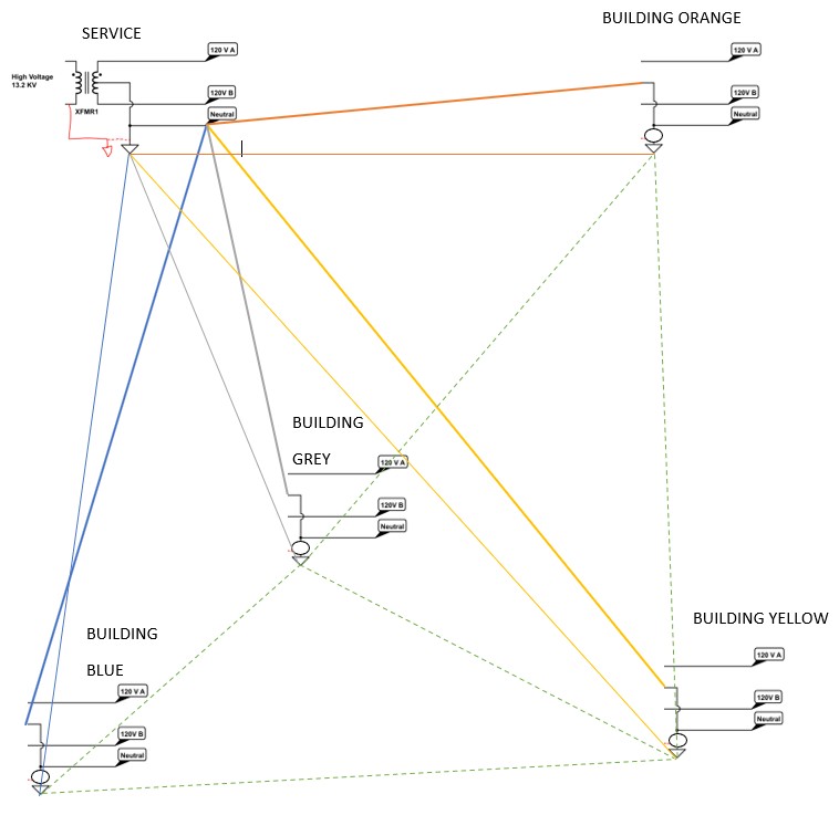
The problem that causes the vast majority of avoidable stray currents in the ground system. Every service is grounded to create a reference plane at the site. Every site has a different reference relative to the power plant (the further away, the higher the reference ground voltage given all other things equal.) In NEC revisions prior to 2008, farm sites were allowed to run 3 wire services (H-H-N) to out buildings from the main pole and have the N-G bond at the buildings. In the US, the most common single phase setup is a center tap 240V where the power supply transformer producers 240V and the center tap results in 240 A-B and 120 A-N and 120V A-N and N-G=0 at the N-G bond.
Now imagine you have a farm site with 4 buildings (ORANGE, BLUE, GREY, and YELLOW) and feed 3 wire service to each building. Some of buildings have imbalanced loads (A current does note equal B current) so N current is A-B.
On the YELLOW shed you have 30,20,10 (A,B,N),
GREY shed is 20,30,-10 (A,B,N),
BLUE shed is 100,50,50 (A,B,N) and
ORANGE shed is 40,40,0 (A,B,N) and it is balanced.
Since you have a N-G bond at the pole that is your ground reference and thus N is 0V at the pole.
With the 3 wire services:
At YELLOW shed there is a 10A current on N resulting in a 1V drop on the YWn wire to SRn and thus YWvG-SvG=1V so a micro current flows thru the earth from YWvG to SRvG (thin yellow)
At GREY shed there is a -10A current on N resulting in a -1V drop on the GRn wire to SRn and thus GRvG-SvG=1V so a micro current flows thru the earth from GRvG to SRvG (thin grey)
At BLUE shed there is a 50A current on N resulting in a 2V drop on the BLn wire to SRn and thus BLvG-SvG=1V so a micro current flows thru the earth from BLvG to SvG (thin blue)
At ORANGE shed there is a 0A current on N there is no voltage drop on the ORn wire to SRn and thus ORvG-SvG=0V so no micro current flows thru the earth from ORvG to SvG (thin orange)
Since all the ground rods in the yard are at different voltages, micro currents also flow between the the ground rods of the buildings (dashed thin green lines) in 3wire diagram.
Now if you break the G-N bond at every building and add a ground wire from the SERVICE to every building (thin wires) you will find that the Neutral voltage is still elevated at every building, but the grounds all remain at 0V which results in NO earth micro currents = no stray voltage. This is what a 4wire setup is. The purpose for the GROUND is to send fault current back to the SERVICE not serve as a conductor. With the older 3 wire setups, the ground rods made the EARTH a conductor that carried a small amount of the current back to the SERVICE, with the 4 wire setups the only time the ground rods are elevated above the 0V is in the case of a fault, which will generally trip a GFCI and then the voltage returns to 0V so the stray current will only exist for mS not all the time.
I hope the illustration makes it apparent that additional ground rods will not eliminate the elevated G voltage at a building. The ways to lower the elevated G voltage at a building is to increase the N conductor size, to eliminate the G voltage you have to balance the loads so N current is 0A or break the N-G bond and run a dedicated G wire back to the service. The 3 wire set was a means of saving money by not installing the G wire to every building, in the end it likely cost more due to the stray voltages that resulted in reduced livestock performance.
There also exists a stray current from the transmission system, but that can be minimized thru the use of an isolated transformer and that depends more on where you sit on the grid and will not fix the issues generated by the 3 wire system on ones building site.
 (Capture 3WIRE (full).PNG) (Capture 3WIRE (full).PNG)
 (Capture4WIRE (full).PNG) (Capture4WIRE (full).PNG)
Attachments
----------------
 Capture 3WIRE (full).PNG (59KB - 29 downloads) Capture 3WIRE (full).PNG (59KB - 29 downloads)
Capture4WIRE (full).PNG (59KB - 31 downloads)
| |
|
 Putting hydrant near power pole?

