|

Cedar Rapids, Iowa | I've been doing printed circuit board design for a couple years, thought some of you might like to see the process.
I start with a schematic of what I want. Each "part" in the circuit has a logical layout for the schematic and a physical footprint indicating the location of every pad, hole, and line that will go on the actual circuit board. Connections are made between the pins of various parts in the schematic, and the design software keeps track of the connections when doing the physical layout.
The board in the following pictures is 3.90 x 3.20 inches and consists of two layers, meaning there are two sheets of copper separated by the fiberglass in the middle. Copper can be removed from each layer to isolate some area, which forms a wire, commonly called a "trace". They can also drill through the board to connect the copper from one side to the other, which is called a "via".
Once the dimensions are determined, the parts are placed so they fit, and then wired together. The design software is really helpful with making sure that the things that need to be connected are, while not being connected to anything else. It is a bit of a maze at times trying to figure out how to route the connections from one place to another.
Once the layout is done and double/triple checked, you export some files and send them to a company that will manufacture the board. Most board manufacturing is done in China, although there are some US manufacturers. I have used both, depending on price and how quickly I want the board. I used a Chinese manufacturer for this board. Design files were sent to them on August 13th, they shipped it on the 18th, and it was in my mailbox on the 29th. Total price was $29 and for that I got 11 identical boards, although I'll probably only use one. The US manufacturer that I use would have had the boards here 5 days faster, but their price for this board was $62.
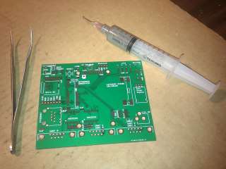
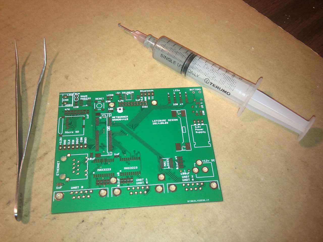
This board has some surface-mount components on it, which means I'll be using solder paste. This is a gray gel that is made up of tiny balls of solder. You put the gel on the pads, the components stick to the gel, then you heat the whole thing up and the solder melts like normal solder. The syringe of solder paste and an angled tweezers to place the parts. I'm doing this by hand, but anything mass produced would have this step done with a robot. They're much faster and consistently accurate.
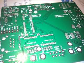
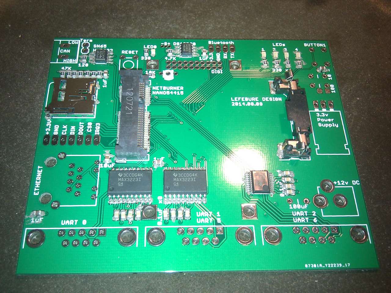
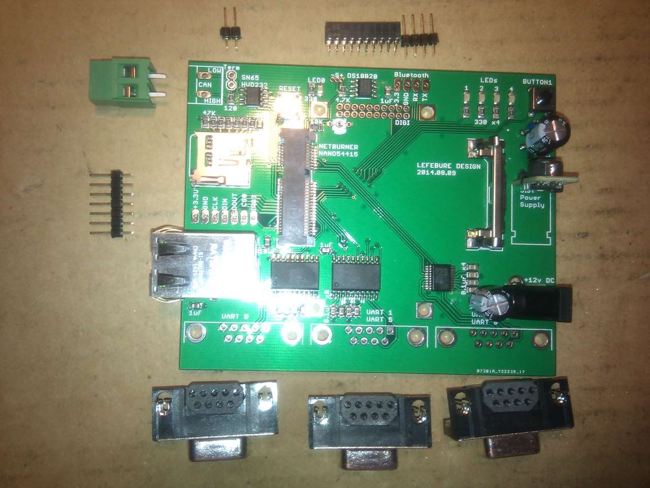
Now with the parts placed on the board, but not heated. The smallest resistors on this board are size 0805, which are 0.079" on the longest edge. Believe it or not, they have 4 digits printed on top to indicate their value.
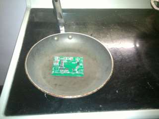
The board carefully goes into a thick skillet and that goes on the stove top. Turn the stove on and watch the solder melt. Timing is critical here, as it cannot get too hot or the parts will break, and it needs to cool slowly. When it's done cooking, I leave it in the skillet to cool. The heat from the pan will slow the rate of cooling. In case you're curious, no, I don't cook food in this skillet. This is used for circuit boards only.
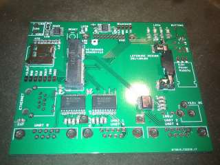
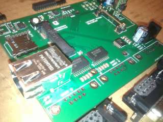
Now that the surface mount components are done, time for some close inspection to make sure that solder didn't bridge between two contacts. Any issues can usually be corrected with a hand held soldering iron that has a small tip.
If everything looks good, we can add the components that need holes through the board. These are soldered by hand with a soldering iron. These are larger parts, so they're easier to do by hand anyway. I start with just adding the components needed to power up the circuit, then do some basic testing with the power on.
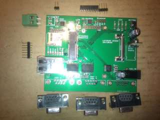
Same step, but a different angle.
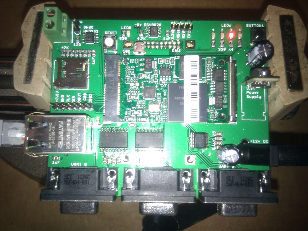
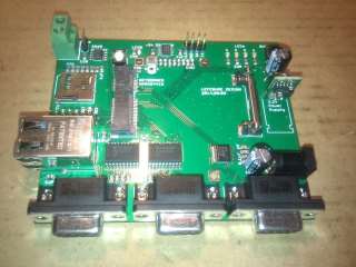
Now I add the rest of the through-hole components.
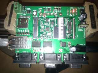
Finally, powered up and running software that makes an LED light up. Now the process of writing software begins.
 | |
|
 Building a circuit board (with pictures)