|
|

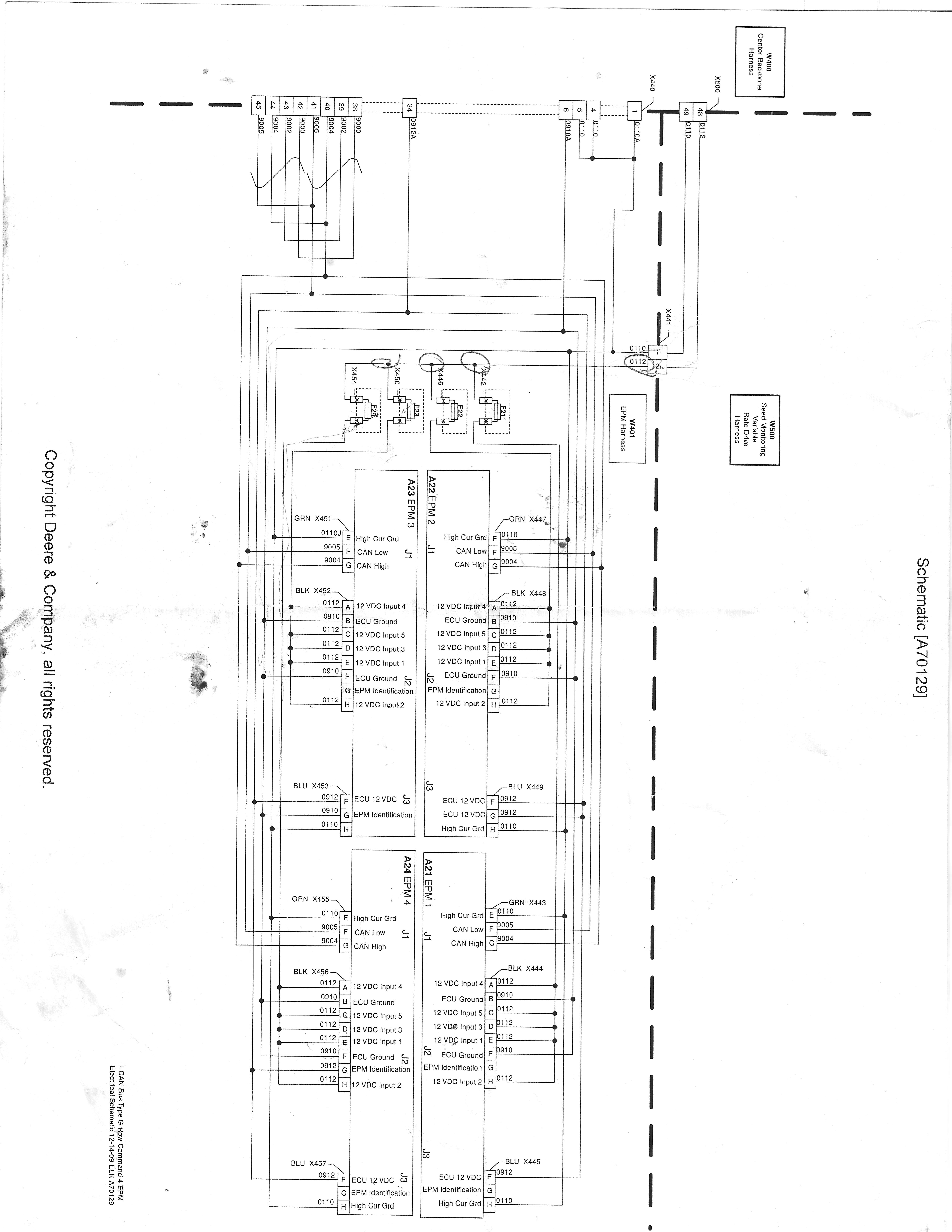
| I have a wiring diagram for our planter. I modified our planter based upon the wiring diagram and the results were not as I expected. In order to achieve the ability to view it clearly after scanning it, it had to be a fairly large file. The diagram can be downloaded here (might be best to right click and "save link as") if you're interested. Our 2630 display showed 10.5 volts on the diagnostics display for the EPM's on Input 1, 2, 3, 4 and 5 whenever the clutches on the planter turned off. If I went back to the fuses that supply power to the EPM's and measured voltage with a Fluke multimeter, the voltage matched what the diagnostics display said. I ran a heavy wire (10 gauge, I said 8 gauge in another thread but it's actually 10 I realized after looking again) to those fuses, thereby pulling the power supply for input 1, 2, 3, 4 and 5 off of the planter harness. Now when I shut the clutches off the voltage on the diagnostics portion of the display in the cab reads about 11 volts while the voltage on the multimeter reads 11.9 volts. Can anyone explain why that is the case? I would think the voltage at the fuses should read the same with the multimeter as what the diagnostics display in the cab shows. I really really want to get the voltage to the EPM's up to 12+ volts according to the diagnostics display in the cab before I put the planter away for the year. Can anyone help me with that? Thanks.
Edited by dpilot83 6/13/2013 18:37
|
|
| |
|
| I thought canbus only used 5 volts. |
|
| |
|
| I believe the communications portion of it does but the modules themselves operate on 12V. |
|
| |
|
| I guess the reason I would like someone who understands CAN systems to look at it is because I don't want to try to boost voltage in a location that will cause damage to the system. There are CAN components on the system so I feel like I'm playing with fire just a little. |
|
| |
|
Leeds, North Dakota | Can bus system is appx 2.5 volts, needs a Clean ground and good clean connections, if harness has been modified, gonna be issues, yellow and green wires for can bus if I remember correctly, shoot me a email, look at post below, Scott. |
|
| |
|
Leeds, North Dakota | dpilot83 - 6/13/2013 19:08
I guess the reason I would like someone who understands CAN systems to look at it is because I don't want to try to boost voltage in a location that will cause damage to the system. There are CAN components on the system so I feel like I'm playing with fire just a little. |
|
| |
|
Litchfield, NY | Connector X441 has pin 1 and 2, What voltage do you have there? How aabout at connector X500 pin 48 and 49? I beleive your CAN system is fine, You cant get 12 volts to and from your inputs. Clean gounds and clean connectors will increase voltage because voltage drops thru resisted (corroded) connectors. I am not familiar with this so tell me where connector X440 and X500 come from? |
|
| |
|
| Connector 441 is just a 2 pin metri-pack (think that's what it's called). We were thinking along the same lines that you were a few days ago and measured voltage there. It was exactly the same as the display diagnostics screen said (10.5-10.6).
Next we tried to find X500. We have a legend that goes with the diagram and x500 was corresponding to SMVR. We found a connector labeled SMVR. It was a white molded connector and you had to remove one bolt to take it apart. There were probably 20 or so 16 gauge wires in that connector. I couldn't believe they were trying to run 16 all the clutches with a 16 gauge wire so I assumed either we didn't understand the diagram and legend or the dealer had given us the wrong diagram for the planter or that was the reason we had low voltage.
My solution was to run heavy wire from a solenoid I rigged up in the planter to the fuses that are right before X441. In other words I bypassed all the planter harness. It helped some, but after we did that the voltage at the fuses no longer matched the voltage on the diagnostics screen of the display. In fact, the voltage at the fuses ended up being 0.9 volts higher than what the display said the inputs were. I was and am very confused by that. |
|
| |
|
Litchfield, NY | What if you hooked a 12v battery directly to the X441 connector? This would eliminate X500 connector and all other connections between there and battery?
Edited by Followme 6/13/2013 21:45
|
|
| |
|

NE WI | Possible there is a snubber diode for the clutch coil so the driver doesnt get a spike of back EMF when you collapse a coil voltage. |
|
| |
|
Leeds, North Dakota | Daniel, why isn't mother deere working on this 3 years, HMMM, Scott. |
|
| |
|
| We have a Case Steiger 400. John Deere is claiming that the Steiger's 200 amp alternator doesn't have to capacity to keep up with a Deere tractor. "We only have this problem with Case tractors". The only solution they have pursued on any planter that has this problem is to go in to the Tech menu on the display and adjust the point at which the display gives you a warning for low voltage. Doing any real diagnosis on why there is low voltage has not been something they have been willing to pursue. I have had to absolutely pull teeth to even get the wiring diagrams so I could attempt to diagnose it myself. |
|
| |
|
| I believe what I have done goes further than that. I hooked 12V (11.9 according to volt meter even when the circuit was under load) to the fuses which are closer to the EPM's than X441 is. That is what made the fuses read differently than the diagnostic menu on the display in the cab. Before I did that the voltage at the fuses was the same as the voltage on the diagnostic menu of the display in the cab. |
|
| |
|
| What I said implies they said something different than they actually did. What they said was: "We only have this problem with Case tractors. It's a problem with Case electrical systems." They did not specifically say that a 200 amp alternator can not keep up. |
|
| |
|
| John Deere is much better equiped to diagnose this problem than I am. If they were willing to do it, I would let them. However, they are not willing to do anything other than adjust the point at which the monitor says "low voltage on EPM's". |
|
| |
|
Litchfield, NY | Have you ran a large ground wire from x441 to the battery ground? If you give it 12volts on the input its got to get back to the battery on the ground side. What part of the CaseIH system are you using? ISO plug???
Edited by Followme 6/14/2013 15:10
|
|
| |
|
| I did upgrade the ground wire on 441. Should have clarified that.
The only part of the setup that is Case is the alternator and the battery. I even upgraded the power and ground wire on the 7 pin just in case.
We have a JD tractor harness in the cab and it doesn't even plug in to the amp connectors in the cab because I re-wired the tractor harness so that it goes to a heavy solenoid for switched power and to the battery for constant power. |
|
| |
|
Litchfield, NY | Tier IV Steigers use one battery for cab functions etc and the other battery in series to start and run SCR system. |
|
| |
|
| Yeah. All of my 12V stuff comes from the positive and negative jumper terminals. There is very heavy wire running from the back battery post to those terminals which makes it really easy to get good voltage there. |
|
| |
 Does anyone understand wiring diagrams that involve CAN communications?

