First off need to clarify which belts. The belts from the engine to the primary counter shaft /electric clutch (under the seat) need tightened and the belt traps need adjusted according to the book. Some of these trap bolts are tough to reach unless you have really long arms. I don't believe these are the belts you are referring too though. The traps are very important to keep from burning and scuffing the belts when disengaged. On the opposite side of the machine you have the wide cogged belt from the primary counter shaft down to the adjustable cylinder speed intermediate pulley. I think this is the belt you replaced ? There should be some discussion about adjusting the sheaves for the proper dimensions. I don't have my book in front of me at the moment but I think there are some measurements of distance between the sheave halves that are needed for proper belt gripping. Then there are the cylinder drive belts on that same side which is really the 4 belts with a bonded backing on them. These are the ones I think you ruined ? I've never had them roll off the sheave before but have had issues with tearing the common backing off the 4 segment belt and breaking the tightener J bolt. In my case my issues were not so much misalignment with anything but wear in the bushings inside the intermediate pulley and rough spots on the sliding ramps inside that change the speed that were grabbing and releasing as well as some slug feeding of green stemmed beans. 

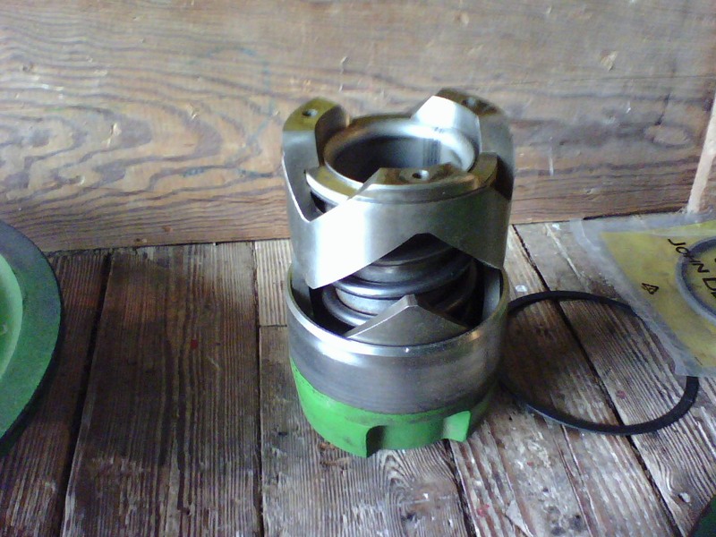
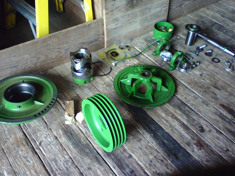
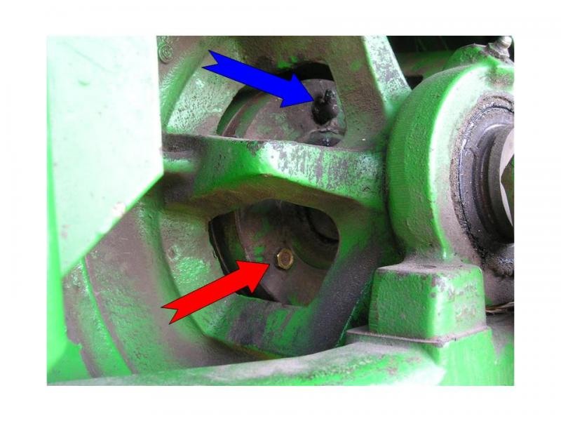
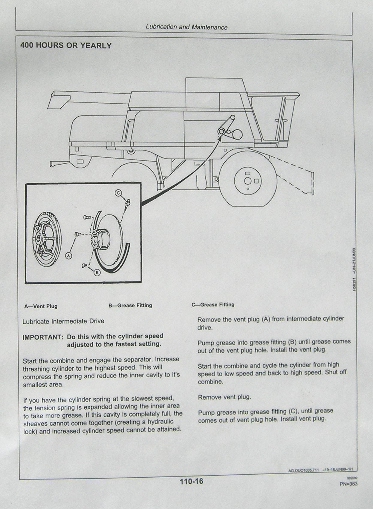
If the ramps get rough or dry from lack of grease they can grab and release instead of sliding smoothly which can transfer shock loading to the cogged belt and 4 segment belt which can damage either of them. If you need to take this variable pulley apart BE CAREFUL as there is a lot of tension on that internal spring. Make sure you get informed about how it comes apart and what to expect. It's good to speed up and slow down the cylinder speed a few times a day to keep grease distributed on those ramps in side the housing. Slug and uneven feeding can also cause shock loading of these belts. Here is a earlier thread with a lot of good info. on it with additional things to check and look for. http://talk.newagtalk.com/forums/thread-view.asp?tid=62445 Special attention on the Lil Hoss post about the greasing procedure in that thread. http://talk.newagtalk.com/forums/thread-view.asp?tid=62445&=1#M440409 There is also a procedure for filling the cavity on the intermediary pulley which is not well defined in the earlier books. This is a copy and paste from my Titan II combine wiki. (now offline) I was finally able to talk to an experienced mechanic that described the importance of the removing the vent plug and pumping the intermediate pulley full of grease annually. As the ramps inside sit in one place while running the grease eventually is removed from the sliding ramp area and these surfaces can try and weld themselves together and grab and release sending a severe vibration through the machine that seems very serious but yet can then disappear. The cure is to annually remove the brass breather plug in this pulley housing as indicated in the picture below by the red arrow and pump grease into the housing with the zerk indicated in the picture below with the blue arrow until grease appears at the breather hole. It also helps to open and close the pulleys at least once a day to help redistribute the grease onto the steel ramps inside. The housing should hold somewhere around 2 tubes of grease. In my case it took a full tube before grease appeared at the breather plug. These instructions are not in the operator manuals for the Titan machines, the 9000 series or the 9010 series. It was not until the 50 series machines that this was added to the operators manual. I feel this is an important piece of information that needs preserved and shared for all the mentioned machines as they all operate on the same concept with the variable pulley and ramps. The mechanic that pointed this out to me was kind enough to make a copy of the page from the newer manual and laminated it for me to include in my operators manual. I have attached a picture of it here so it can easily be read. Be sure to note this procedure should be done with the cavity at it's smallest size which is with the pulley at it's fastest setting. 

I'm sure others will be able to elaborate more on possible issues. | 

 JD 6620 Cylinder Drives Alignment