This is a long post I know, but if you understand electronics fairly well, I'd sure appreciate it if you bear with me. I am working on a JD 4840 that's having a problem with the battery draining overnight. It still has two 6V batteries connected in series for a 12V system. In addition to the tractors normal electrical system I have an auxilery power box that I wired up so that I didn't need to have 5 or 6 wires running to the battery with all the monitors we have in the cab now. You can see a simple diagram of how things are set up below: 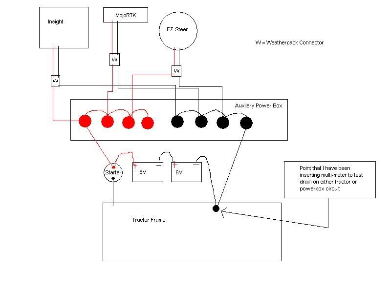
I don't have my camera with me now so I had to take a picture of the MY-68 Multi-Meter that I have with the webcam on my computer so it isn't a good picture but here is what the controls and connectors for the leads look like: 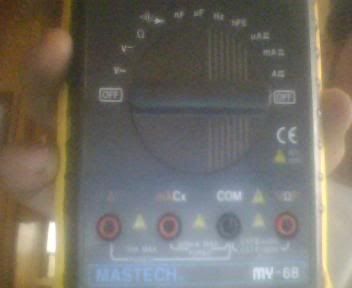
I always have the negative lead connected to the COM shown in the picture above. I have tried having the positive lead connected to the "A" (far left) and put the ammeter on the A setting which is right above Off on the right side. When I do it this way I've never seen it settle down to anything other than -.01 to -.02. It doesn't matter if I have the other end of the leads connected in series with the ground cable and tractor frame or if they're just dangling in mid air. If I put the positive lead in the mA hole (second from left) and set the dial to A it still does the same thing. If I set the dial to mA it reads .29 mA between the ground from the battery and the frame and it reads .02 mA between the ground for the auxillery power box and the frame. If I put change the dial to uA (I don't know how to make the symbol for micro amps.....10-6 amps) it says 256 uA between the ground from the battery and the frame and .2 uA between the ground for the auxillery power box and the frame. Between the auxilery power box ground and the frame the reading is always negative. Between the battery ground and the frame the reading is positive if I put the positive lead on the ground stud on the frame and negative if I put the negative lead on the ground stud on the frame. I don't understand that. I also don't understand why it appears that there is a much larger draw between the battery negative and the frame than the auxilery power box negative and the frame, but if you rub the ground cable for the battery against the stud it does not spark and if you rub the ground cable for the auxilery power box against the ground stud it does spark (small sparks but sparks nonetheless. I also thought that all of the power draw that I've seen is well below what would drain your battery but maybe I'm wrong. What is the maximum allowable drain for this type of a thing? Any help you can provide would be much appreciated. Thanks.
|  Electrical Gurus - Mastech MY-68 multi-meter (battery drain diagnosis)

