| AgTalk Home | ||
| ||
 Wiring a magnetic starter with thermal overload protection Wiring a magnetic starter with thermal overload protectionJump to page : 1 Now viewing page 1 [50 messages per page] | View previous thread :: View next thread |
| Forums List -> Machinery Talk | Message format |
| dpilot83 |
| ||
I'm pretty dense when it comes to AC wiring so please bear with me. I had an 80 gallon vertical tank that I was just using as sort of a buffer air supply. Recently I decided to go ahead and put a compressor and motor on it. So I got a motor (5 HP single phase), compressor, magnetic starter with thermal overload and a pressure switch from North Central Air in Downs, KS. Wiring this thing up is really exposing my ignorance on AC stuff. I think I'll explain how I think it works so those of you who are knowledgeable will correct what I don't understand. First of all you've got just regular old 220 volts (or is it 240? I seem to remember putting a voltmeter between the two legs and actually getting something like 246. Is this OK? I guess I'll keep calling it 220) coming from the wall. My understanding of 220 is that the black wire is hot half the time, the white wire is hot the other half of the time and the green wire is ground. Already we bump up against my limited understanding. I thought when the black wire was hot the white wire completed the circuit and when the white wire was hot the black wire completed the circuit. So what is the need for the green wire at all? When does current flow through the green wire? Also, how does this reversing polarity not reverse the direction of the motor? I'll move on. So as far as I can understand it, the power comes from the wall, through the cord to what I call a contactor (I've replaced them on center pivots and I'm just always careful to wire them up exactly the same as it was before I got to it). A contactor seems pretty simple. A low amperage signal (from the pressure switch) actuates a coil which closes the circuit for one or multiple wires. In this case only two wires are hooked up because we're single phase 220. So now I'm attempting to logically think through how the pressure switch activates the coil. The pressure switch only has two conductors going to it. One would want the conductor going to the pressure switch to be "hot" 100% of the time. Now how would that be accomplished? On 220V you've got alternating current so let's say you hook L1 on your 220 to the switch. Wouldn't that wire be hot 30 times per second and then dead the other 30 times per second? Is 30 times per second of it being hot enough to hold your coil in place? I'm going to assume that works for the sake of continuing on. So the next step is to hook the other side of the pressure switch to provide power to the coil. Then you have to make sure the coil has a ground. Hmmm. Maybe that's the solution. The other side of the coil would be connected to the other leg on the 220 so the other half of the time the coil is still hot, but with the other leg? Does that not mess it up if current is flowing through the coil the wrong way? Continuing on. After you've got the coil closed and you've got both legs moving towards the motor, you've got to get through the thermal overload first. It appears to me that the thermal overload is wired directly to the contactor. I don't really understand how the thermal overload works. How does it fail? It somehow senses whether the motor is heating up and when it senses that the motor is heating up it breaks the circuit. Do you have to replace the thermal overload device at that point or is it some spring loaded deal that resets itself? Do you have to manually reset it or does it start again once the motor cools down? I would think you would want to have to manually restart it if it is able to be reset. Once you're through the thermal overload you go to the motor. Dad has a compressor very similar to mine and his has the exact same motor on it. It has wires labeled T1 and T5 that go to the black wire and it has wires T4 and T8 that go to the white wire. The green wire of course grounds the motor housing (which like I said I don't really understand). My question here though is why do you connect one leg to two wires and another leg to two wires? Why are the wires not connected back inside the motor so that you only have to connect one wire to another wire rather than connecting one wire to two wires? What does T4 do vs T8? What does T1 do vs T5? Anyway, that's my limited understanding. If anyone has taken the time to wade all the way through it, I really appreciate it. I've found that if I try to explain something it really shows the holes in my knowledge and I would really like to understand it so please help me shore up the weak areas. Thanks. | |||
| |||
| IADAVE |
| ||
| Not much help but every thing will work if you don't hook up the green ground. The bad part is if something shorts to the frame the frame will be hot. There is always 110 between the 2 wires( black and white) and the green ( ground). There should always be 220 between the black and white. The current alternates direction fast enough you can't tell. Maybe a better way to say it is to visualize 3 wires. black green and white. Lay the green wire in the middle. The white wire is 110 volt difference to the green. the black wire on the other side is also 110 volts different from the green but the other direction from the white. The thermal overload is typically 2 pieces of metal that expand with heat. The metal expands at different rates so when it gets to a certain temp it breaks connection. Not a very precise description but will give you a rough understanding of my understanding. LOL Once you get in the motor I am at a loss other than changing ( I think T5 and T8 )with each other will change the rotation of the motor. Hope fully some on will come along with a better explanation. | |||
| |||
| benc |
| ||
SE Michigan | Like IaDave said quit worrying about the alternating current it happens so fast you do not observe it or have to worry about it. I have not seen your contactor, but L1 in most cases would only be hot when the contactor is engaged to make the motor run. The extra wires in the motor are so that you can change the motor from 110 to 220 and there should be a sticker or name plate on the motor giving instructions on which wires to connect to which wires to make the motor run on either voltage. Also changing wiring can make the motor run in reverse this should also be on the motor.. Now where the cord or feed cable comes in to the enclosure there should be some terminals to connect them to might be labeled T1 and T2 but different mfg might use different labels. One wire should go from T1 to pressure switch then another wire from pressure switch to operating coil then other wire from operating coil to either T2 or ground depending on the voltage of the operating coil. If it is 220 go to T2 if it is 110 got to ground. You need the green wire connected to the metal of the enclosure and also to the motor for safety and to comply with electrical code. If your operating coil is 110 to be legal you need to run a 4th wire for the ground of the coil. | ||
| |||
| WTW |
| ||
Winkler, Manitoba Canada | Benc, You have that backwards. L1 an L2 are the power supply connections and T1 and T2 are the connection points for the motor. The L connections are typically at the top of the starter and the T connections at the bottom. As a result most of your post is not correct and actually dangerous! Edited by WTW 4/23/2013 16:42 | ||
| |||
| lylefarm |
| ||
East of Dowagiac Michigan | Some bad art to make it work, (still should have a few things grounded for safety) assuming that you have a 110 volt coil on the contactor......if you have a 220 volt coil green wire goes to the white line wire. (contactor.png) Attachments ----------------  contactor.png (11KB - 685 downloads) contactor.png (11KB - 685 downloads) | ||
| |||
| Gerald J. |
| ||
| Not enough information to tell accurately. There are two scenarios depending on the contactor coil voltage. If the contactor coil is 120 volts you NEED 4 wires to the unit. Green for safety ground, white for neutral, plus red and black for the two hots. So long as there are no shorts, green has no electrical function except to protect YOU from shock. For a 120 volt coil, you bring red and black to the contactor line terminals. You add a jumper from one line contact to the control circuit. The control circuit starts with one of the control terminals on the thermal protector, then from the other control terminal (and there can be two thermals but single phase only needs one) that circuit goes to one terminal on the pressure switch, and from the other terminal on the pressure switch, to one coil terminal. You can add a manual control switch to that circuit most anywhere in the series circuit to turn the compressor on and off. The second coil terminal goes to white, the supply neutral. It works but its not correct to use black, white, and green or bare for 240 volt load. White should always be neutral, using it for a hot will cause someone to be hurt some day. If the coil is 240 volts the control wiring is the same except the second coil terminal goes to the other line terminal, not the neutral supply wire. In either case the contactor load terminals each go to a line terminal on the thermal protector, and the two working motor leads go to the load terminals on the thermal protector. Its not critical which 240 volt wire is which so long as you don't short them. The single phase motor runs the same direction no matter how they are crossed. That's not true in three phase. The thermal protector has a heating element that heat sup from the motor current, when the motor current is too high they open their control side and drop out the contactor. If its still beyond you go hire an electrician for your shop and your personal safety. Gerald J. | |||
| |||
| dpilot83 |
| ||
Gerald J. - 4/23/2013 18:20 The thermal protector has a heating element that heat sup from the motor current, when the motor current is too high they open their control side and drop out the contactor. Thanks. I asked North Central air about how to set the adjustable thermal protector. They said to leave it where it was set and if it ever shut down during normal operation, turn it up a click and try again. My thoughts are that if it does not fail while you're sitting there watching it go through a cycle it would be better to turn it down a click and then let it go through a cycle again. Keep turning it down until it does fail, then turn it up a click or two. To me it should be set for a normal load so that if the pressure switch fails or something like that the compressor would shut down before major problems occured such as the compressor trying to blow hoses or something even worse, the tank. I guess that's what pressure relief valves are for but if the pressure relief valve fails you could have a problem and if it works the compressor might run for days if someone forgot to turn the compressor off before leaving the building and going on vacation. This would result in an eventual fire I would think. Another question I have is in regards to color coding things. We had the shop wired by an electrician and I noticed that he used nothing but black wires in his wiring process. The wire was in conduit and he just ran black wire at least for the 220V circuits. Is that a common practice? | |||
| |||
| dpilot83 |
| ||
I really appreciate your explanation. I was under the impression that the thermal protector was almost another contactor in a way. I thought that if it tripped then something mechanically opened the circuit within the thermal protector but you're saying that it is basically another low amp switch that shuts the contactor down. So if the contactor fails, there really is no protection against that? This seems odd but I suppose a contactor failing in the closed circuit position would be extremely rare. | |||
| |||
| dpilot83 |
| ||
I've read your description multiple times and I believe it makes perfect sense to me a this point. However, I am confident the compressor I bought for my Dad's shop which came assembled and wired (except for a power cord) is not wired like that at all. His has a control circuit that consists of nothing more than the pressure switch being wired from L1 to the switch and then from the switch to one of the coil terminals. The thermal overload circuit is separate. I'm going to go look at it again and make note of the thermal overload wiring. | |||
| |||
| WTW |
| ||
Winkler, Manitoba Canada | Using two black wires for a 220/240 volt circuit is quite common. | ||
| |||
| dpilot83 |
| ||
| What about 3? The safety ground is also black in the conduit. | |||
| |||
| WTW |
| ||
Winkler, Manitoba Canada | On single phase motors the thermal overload is often simply a device in the motor itself that breaks either of the lines. The method that Gerald J. described is very typical of the way thermal overloads are connected in conjunction with a magnetic starter. It is not very common for terminals on a magnetic starter to burn on in the connected position. I have never seen that occur, but I imagine it has happened. I have Allen Bradley mag starters on my drying setup and have not experienced any failures in over 30 years. | ||
| |||
| WTW |
| ||
Winkler, Manitoba Canada | The ground would typically be a size smaller than the power carrying leads, so an eletrician should recognize this. Code hear would require at a minimum that the ground be identified at both ends with green electrical tape if a coloured wire other than green was used. | ||
| |||
| Greener |
| ||
Ontario | The thermal overload work on heat produced by current going through them. Most applications require you to manually rest the overloads. Almost all farm duty motors that I have seen actually have an overlad on the motor itself (so oversizing of the overload is not done)breaks the one phase of the circuit causing the circuit to be open and no current can flow.the simplest way to run your magnetic contactor is to have a coil that is 220 and a pressure switch that is rated at 220 volts (normally ratings are 250 volt). Ground is for safety so if there is a short to frame of motor it will provide an unlimited current at low resistance path to ground so the breaker or fuse will trip in the shortest time possible, ideally in a half or quarter of a cycle. That way no metal part will become "live". | ||
| |||
| dpilot83 |
| ||
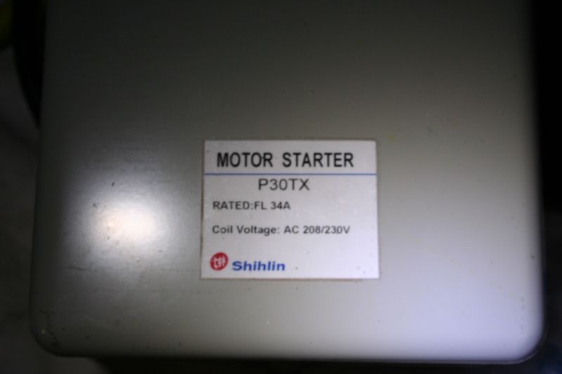
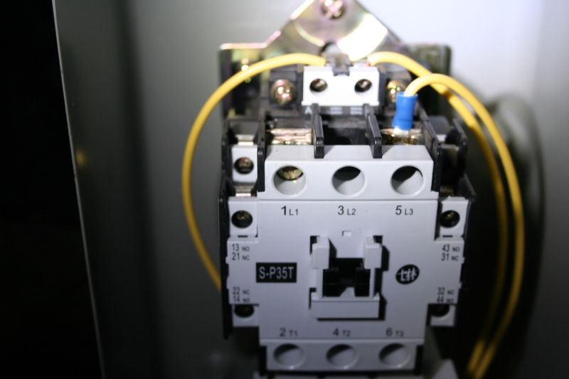
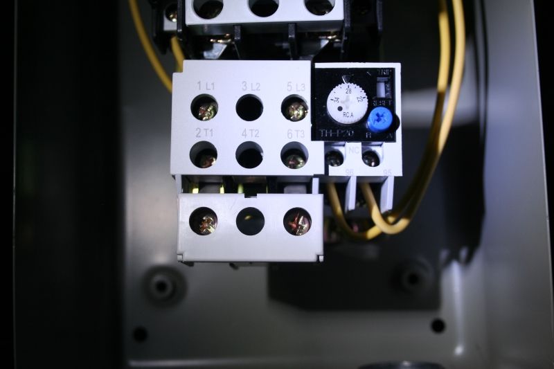
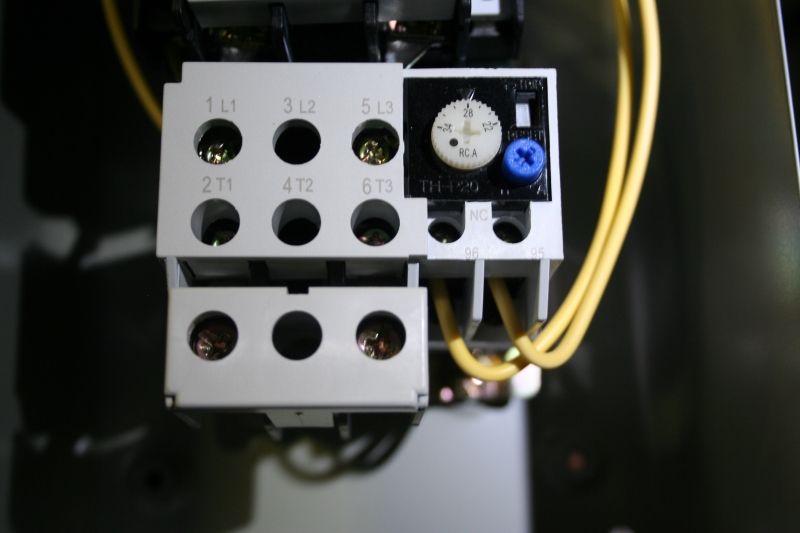
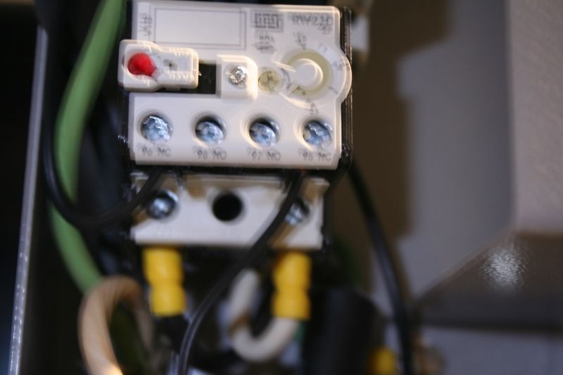
Well, I guess I'm going to post some pictures just to add clarity. The first set of pictures will be for the compressor I use:
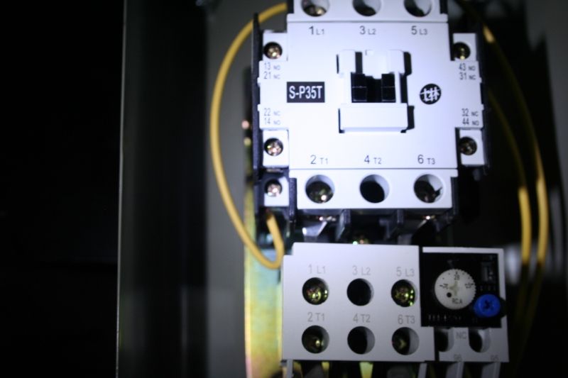
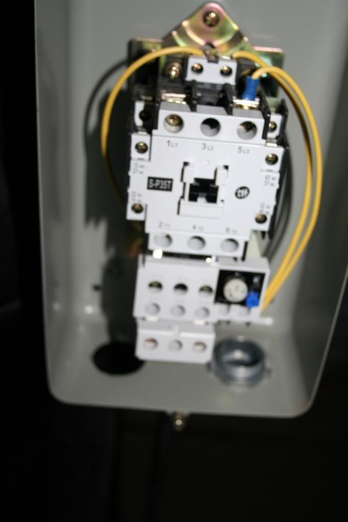
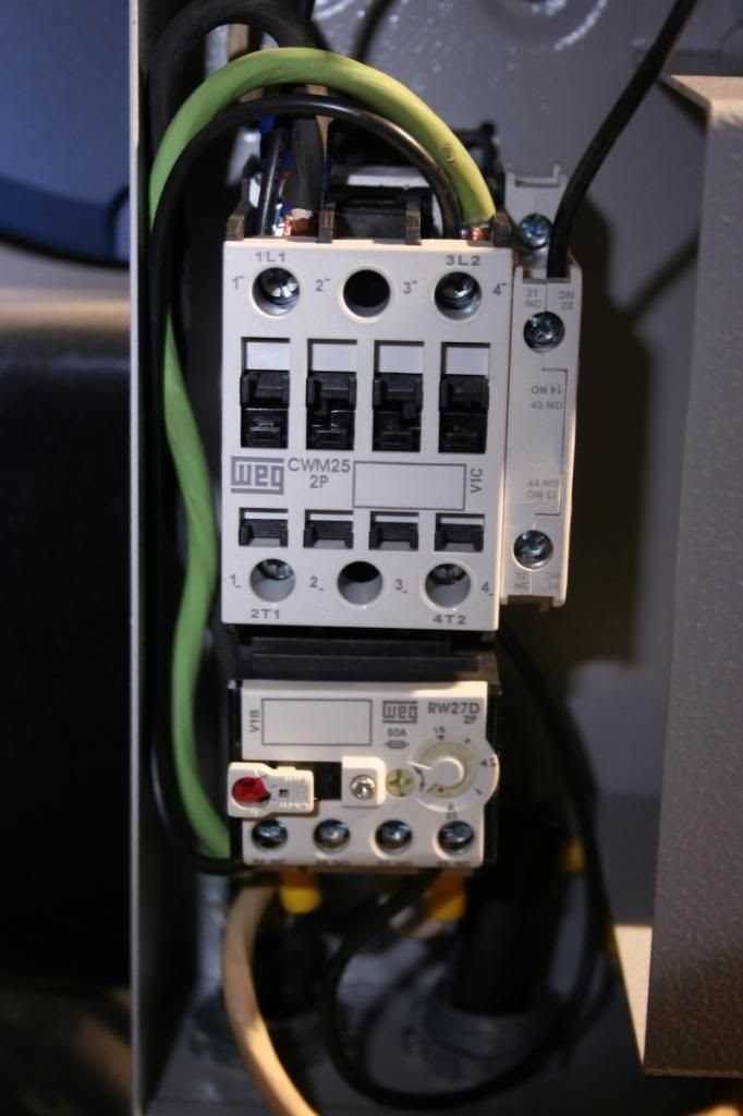
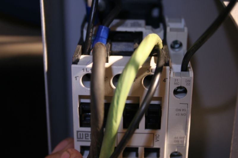
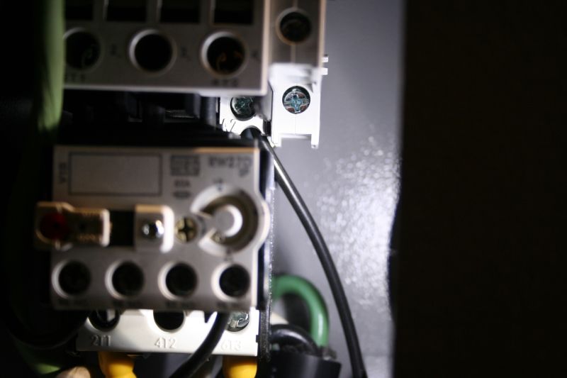
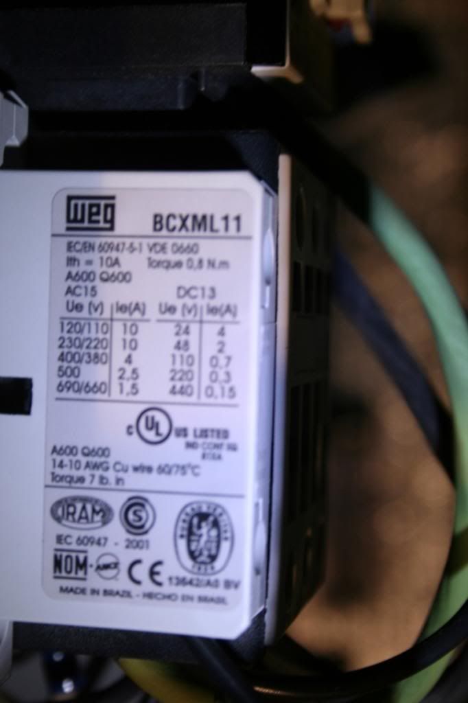
The second set of pictures below are from the compressor Dad uses. I will only say that I did not wire the power cord. lol
| |||
| |||
| Gerald J. |
| ||
| In the past, thermal overloads were set by changing the heating element. Each maker had a chart for each model showing motor running current and the appropriate element. It was not unusual for an electrical distributor to ask the motor current, then take the one two or three steps higher current to prevent "nuisance" trips. Trouble is when the load is a three phase motor on an open delta supply with the wild leg transformer a little on the small side the motor unbalance gets doesn't get the current high enough to trip but gets it high enough to fry the motor. And when the motor is a 50 hp submersible pump motor in a 500' deep well, the cost of changing the motor is a great deal more than the cost of a few thermal heaters of the correct rating. Motor current will vary with the pressure the compressor sees and the line voltage, usually going higher with low line voltage, unless the voltage gets so high as to saturate the motor's core then the current goes up rapidly even without load. Gerald J. | |||
| |||
| Gerald J. |
| ||
| The thermal protector is for the motor. Most often if a contactor fails, it fails open, it doesn't short to ground. Gerald J. | |||
| |||
| Gerald J. |
| ||
| These things would be wired in series from the coil supply to neutral: The thermal operated switch, the manual control switch, the pressure switch, and the coil. For function it matters not the order or which side of the coil each switch is on for function though codes prefer all switches in the hot side with the load like a coil connected directly to the neutral. That way when a switch is open the load isn't sitting there with line voltage on both terminals to cause an electrician feeling his way around to find there's voltage on both sides of the coil as he tests with a damp finger. Gerald J. | |||
| |||
| benc |
| ||
SE Michigan | WTW - 4/23/2013 16:40 Benc, You have that backwards. L1 an L2 are the power supply connections and T1 and T2 are the connection points for the motor. The L connections are typically at the top of the starter and the T connections at the bottom. As a result most of your post is not correct and actually dangerous! WTW You are so right I did reverse the L1 L2 and the T1 and T2. My thoughts were correct, but I did not put it on the forum correctly. I stand corrected. | ||
| |||
| Gerald J. |
| ||
| Not all who make connections either commercially or on the farm know the code safety requirements, but some understand the circuits and can make things work even though an inspector would tag the assembly "DO NOT USE UNTIL CORRECTED." Another reason for putting all the switches in the hot side is that way no accidental grounds will make the load hot and in this case the motor run, though with a 230 volt coil a ground on the controls shouldn't accidentally pull in the contactor. Gerald J. | |||
| |||
| benc |
| ||
SE Michigan | WTW - 4/23/2013 21:09 The ground would typically be a size smaller than the power carrying leads, so an eletrician should recognize this. Code hear would require at a minimum that the ground be identified at both ends with green electrical tape if a coloured wire other than green was used. WTW I agree with you about the green tape on wires that are a different color than green. I have see bare wire a time or two in conduit also, but not sure about code on that. | ||
| |||
| Mav |
| ||
| If you simplify your analysis of AC power, I think you will find it easier to wire up your circuits. But let me start off by saying that your statements about AC power are not really correct. Both legs (black and white) in a 240V circuit are hot the whole time. If you look at the waveform of each leg independently, they would look identical in regards to their waveforms. The difference between the two arises from one leg being ½ a cycle behind the other one. A simple voltage comparison shows this: Leg 1 to Neutral: 120V – 0V = 120V Leg 2 to Neutral: (-120V) – 0V = (-120V) which we still treat as 120V by itself. Leg 1 to Leg 2: 120V – (-120V) = 240V Now what you really need to do is throw all that garbage about AC power (phase angles, power factors, complex powers, sine waves, etc) out the window, because you will never really use it, and start viewing everything as simple DC circuits. DC analysis is used all the time in AC circuits. In fact, the whole reason for referencing AC power by it RMS value is that it allows one to use simple DC equations to calculate various electrical relationships. All the components you have shown can be converted into simple DC circuits comprised of simple switches and connections. Treat the given AC voltage as a simple DC voltage and everything will be gravy. Good Luck. Also, I believe you need to identify the ends of a white wire with black electrical tape when it is used as a hot leg. I could be wrong about that, but I do not think it will hurt anything. Mav Edited by Mav 4/23/2013 23:24 | |||
| |||
| dpilot83 |
| ||
Alright, I very nearly understand what they did on Dad's compressor (last 5 pictures). One thing I absolutely do not understand (which really is frustrating to me for as much time as I've spent on this) is why did they put a jumper from L1 to 31NC/22NC (the add-on contactor to the right side of the main contactor)? Anyway, if I were going to fix it I would: 1. Change the power cord out for a cord that has a black, red and green. The black would go to L1, the red would go to L3 and the green would go to the ground screw on the mag starter enclosure. Plug end of the cord would be wired appropriately as well of course. Alternatively I would re-configure the current wiring of the power cord so that black goes to L1, white goes to L2 and green goes to the ground screw on the mag starter enclosure. Then I would put black tape on each end of the white. 2. I would run a jumper from L1 on the contactor to 96NC on the thermal overload. 3. I would connect one pressure switch wire to the 95NC on the thermal overload. 4. I would connect the other pressure switch wire to one of the coil terminals. 5. I would connect the other coil terminal to L2 on the contactor. This makes sense to me. What in the world is the jumper from L1 to 31NC/22NC for on Dad's compressor? | |||
| |||
| dpilot83 |
| ||
Thanks. In my situation if I were to do your test I would do it to safety ground instead of to neutral because we have not pulled a neutral line for this 220V circuit right?. I would only need a neutral line if I needed 120 volts as well, correct? I have never understood the difference between the safety ground and the neutral and why both are needed. | |||
| |||
| dpilot83 |
| ||
| Lyle, I'm feeling bad for not commenting on your contribution to this thread. I know even simple diagrams are a pain to make on a computer and then you still have to upload them. The reason I have not yet commented is because the physical layout of my thermal overload in relation to my contactor is different than the way you drew your diagram. Now that I have a better understanding of how it all works I see that while the physical layout is different, your diagram is exactly the same as what I have from a theory of operation standpoint. As I think about drawing my physical layout in a diagram I am realizing it would be difficult to do and that your diagram is an elegant solution to drawing the concept. I'm sure if I had studied your diagram more initially rather than discarding it because it looked physically different than what I have, I would have figured it out faster. Anyway, I wanted to thank you for your contribution. Like I said, I know that takes a lot of time and I appreciate you being willing to go to the effort to do it. | |||
| |||
| Mav |
| ||
| Yes, you are correct on both counts. As you probably already know, the safety and neutral wire are hooked together in the distribution box. Hence they will be at the same electric potential which will give you similar readings on a voltmeter. In regards to the use of a safety and neutral wire, I venture to guess that the reason is it lowers the risk of an electrocution. For instance, lets say you use a white neutral wire for both grounding and circuit completion purposes. Now lets cut the neutral wire and turn the power on to the load. Everything from the break in the wire to the distribution box should be safe to touch. However, everything behind the break can pose a serious electrocution hazard including the exterior surfaces of the components (providing they are electrically conductive). Conversely, if you use both a safety and neutral wire, it would require severing both wires and shorting the neutral to a conductive enclosure in order to make a component an electrocution hazard. Severing only one wire should pose no threat. Mav | |||
| |||
| benc |
| ||
SE Michigan | Mav I think that you have given a good explanation of the difference between the white neutral and the green ground wire. I would just add a comment or two. They serve two different purposes, one is to provide a complete circuit for a 120 function and the other is to provide safety for fault in the hot circuits. Also in most if not all locations it is code and could be denied service if not correct. One last comment I worked with a licensed electrician years ago that did a lot of home wiring. He always wired built in appliances ( Stove top, ovens, dishwashers, garbage disposals, ETC) with an outlet and a cord with a plug on instead of wiring direct. His reason was that at least here the electrical inspector had to stop at the outlet, other wise he could reject the appliance as well as the wiring the electrician did. The inspector was prohibited from inspecting any thing that was plugged in to an outlet that was up to the mfg. | ||
| |||
| WTW |
| ||
Winkler, Manitoba Canada | "Alright, I very nearly understand what they did on Dad's compressor (last 5 pictures). One thing I absolutely do not understand (which really is frustrating to me for as much time as I've spent on this) is why did they put a jumper from L1 to 31NC/22NC (the add-on contactor to the right side of the main contactor)?" The mag starter came with that jumper in place and whoever wired it never removed it. From your pictures it looks like the mag starter you just purchased also has that jumper. That jumper is pretty standard because a lot of mag starters are wired with a stop/start station which requires use of the hold in contact in the auxiallary contact. | ||
| |||
| dpilot83 |
| ||
| Thank you. Now I will go wire it up. I do not like messing with stuff like that until I understand every aspect. As I look at it now it's all extremely simple and I'm ashamed it took me this long to understand it. Thank you kindly to everyone who put up with my slow learning process. | |||
| |||
| WTW |
| ||
Winkler, Manitoba Canada | I would not worry about the fact that the cord does not have a red conductor. Just use the white and black for the lines and use the green for ground. If you like, put some red or black tape on the white at the ends. I do not think you will find a cord with red, black and green coloured leads. If you really want the coloured leads, I think you will need to purchase a 4 wire cord and not use one wire. | ||
| |||
| dpilot83 |
| ||
| Well, thanks much for the help everyone. I wired it up today and it worked great. Only problem was they sent me a 150 PSI pressure relief valve for a 175 PSI compressor. I was sitting there timing it and about jumped out of my skin when that thing went off. Anyway, thanks again so much for all the patient responses. | |||
| |||
| dpilot83 |
| ||
| I just used my core like you said. I should probably put some black tape on it but I'm not so sure I will. | |||
| |||
| Jump to page : 1 Now viewing page 1 [50 messages per page] |
| Search this forum Printer friendly version E-mail a link to this thread |
| (Delete cookies) | |